How to calculate the temperature in a ventilated electronics enclosure
Electrical and electronic components are sometimes housed in enclosures with ventilation openings to allow ambient air into the enclosure to more efficiently cool heat generating components. The most common ventilation configuration is to have openings at the top and bottom of the enclosure as shown in figure 1.
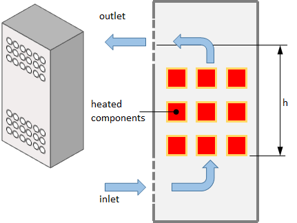
Figure 1. Ventilated enclosure cooled via natural convection
The air flow through the enclosure is driven by the difference in air density of the cooler air outside the enclosure and warmer air inside due to the heat transferred from the heat generating components. As the air flows vertically through the lower ventilation openings and across the heat generating components its temperature increases. As a result components mounted at higher locations in the enclosure will be subjected to air temperatures above the ambient air temperature. Determining the internal air temperature surrounding these components will allow you to identify and relocate components that have a maximum ambient operating temperature lower than the surrounding air temperature. The size or number of the ventilation openings can also be adjusted to lower the internal ambient temperature.
If detailed thermal analysis needs to be conducted on components that have attached heat sinks, the heat sink can be modeled as if it were sitting in open air and the calculated internal air temperature at the heat sink location can be used as the ambient temperature.
As the air flows into, through and out of the enclosure the flow restrictions caused by the inlet ventilation openings, internal components and outlet ventilation openings produce a corresponding pressure drop denoted by ΔPinlet, ΔPcomp and ΔPoutlet respectively.
The difference in density between air flowing into the enclosure and that exiting the enclosure produces a pressure difference ΔPbouyancy. This pressure difference must be balanced by the sum of the pressure drops through the enclosure as expressed in equation 1.

where:


The average density of the air inside the enclosure can be approximated using equation 3.

where:


Substituting equation 3 into 2 produces equation 4 that relates the average internal and ambient air temperatures to the pressure difference due to the change in air temperature.

The pressure drop due to the inlet and outlet ventilation openings (equation 5) is related to the speed of the airflow through the openings and the number of and size of each opening. A representation of a typical ventilation openings is shown in figure 2.


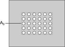 Figure 2. Ventilation openings
The calculation for the fluid resistance coefficient, k is the same as that used in the blog article Estimating Forced Convection Cooled Heat Sink Performance in a Ventilated Enclosure (Part 1). It will be repeated here for convenience.
for Re>105

for 30<Re<105

for Re<30

where:


Note: 

Assuming the heat generated by the components is uniformly distributed, equation 13 can be used to relate the heat transferred to the air inside the enclosure via convection Qconv to the temperature difference of the air leaving and entering the enclosure through the ventilation openings.

where:


With the assumption that the heat generating components are distributed uniformly in the enclosure the temperature of the air increases linearly in the vertical direction through the enclosure. The average air temperature can then be calculated with equation 14.

Substituting the average internal air temperature with equation 14 in equation 4 and combining that with equation 13 results in equation 15, a new expression for the buoyancy pressure drop.

The volumetric flow rate is used to calculate the speed of air through each ventilation opening using equation 16.

In most electronics applications the pressure drop due to the ventilation openings is much larger than that due to the internal electronic components since they are not densely packed. As such ΔPcomp can be ignored for most applications. Combining equations 5 and 16 and substituting the new values of inlet/outlet pressure drops and buoyancy pressure difference from equation 15 into equation 1 gives equation 17. This equation has only one unknown, the volumetric flow rate of the air flowing through the enclosure since ΔPcomp is assumed too small for consideration.

The variables with the subscripts inlet and outlet reference the corresponding variable values for the inlet and outlet ventilation openings. The value of the volumetric flow rate can be calculated using an equation solving function available in most mathematics software or using the goal seek function in MS Excel.
Because there is a linear increase in the temperature of the air along the height of the enclosure equation 18 can be used to determine the air temperature as a function of the height location in the enclosure.

Note that the total heat loss from the components is equal to the sum of the heat losses due to convection Qconv and radiation Qrad. A conservative approach is to assume all the losses are due to convection. However if the component temperatures are high and the ventilation openings are small then radiation may account for 30% or more of the total heat losses.