How to calculate the temperature rise in a sealed enclosure
Often times electrical or electronic components are housed in sealed enclosures to prevent the ingress of water, dust or other contaminants. Because of the lack of ventilation in these enclosures all of the heat generated by the internal components must be dissipated through the walls of the enclosure via conduction then from the external surface of enclosure to the environment via radiation and natural convection as shown in figure 1.
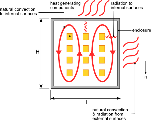
Figure 1. Heat transfer from a sealed enclosure with heat generating components
Accurately calculating the temperature rise of each component housed inside the enclosure is a complicated task that is best accomplished using computational fluid dynamics and heat transfer software. However in many cases being able to estimate the average air temperature within the enclosure based on the dimensions and the material of the enclosure is sufficient information to allow you to develop a design that can be further refined through testing.
The path of the heat flow out of the enclosure is represented by the general thermal resistance network shown in figure 2. The four vertical walls of the enclosure can be considered a single wall by combining the areas of each wall. The top and bottom walls of the enclosure have to be evaluated separately since the heat transfer coefficient of each is different.
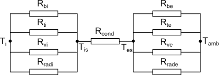
Figure 2. Sealed enclosure thermal resistance network
The heat must first be transferred from the air inside the enclosure to the internal surface of the enclosure walls. Rvi, Rti and Rbi represent the thermal resistance associated with the heat transfer to the internal vertical, top and bottom surfaces respectively. The internal thermal resistances are highly dependent on the number of heat sources, arrangement of the heat sources and location of internal structures that affect the air flow within the enclosure. Because of the variability of these parameters a highly accurate estimate of this thermal resistance using simple hand calculations is not possible. However by making some assumptions regarding the layout of the components within the enclosure a reasonable estimate of the internal thermal resistance can be calculated. The following assumptions will be made:
- The heat sources are evenly distributed throughout the enclosure
- The structures in the enclosure do not significantly obstruct the movement of air flow throughout the enclosure
If there are no fans or other type of forced convection within the enclosure the heat transfer from the internal air to the walls is via natural convection. Correlations used to calculate the heat transfer from horizontal and vertical plates [1] will be used to estimate the heat transfer from the top/bottom surface and vertical surfaces respectively. The equations used to calculate the thermal resistance associated with the convective heat transfer from the air inside the enclosure to the walls of the enclosure are as follows:
Convection to Internal Bottom Surface

where:


Convection to Internal Top Surface
where:

Convection to Internal Vertical Surfaces
where:


Equations 3,6 and 8 are developed in [1] and are only applicable with air as the flow medium and laminar flow. For most electronic applications the flow within the enclosure will be laminar.
Radiation can account for a significant percentage of the heat transfer in situations involving natural convection as is the case with a sealed enclosure. The radiation heat transfer from the heat generating components to the internal walls of the enclosure is represented by Rradi. Since our simplified analysis allows us to estimate the internal air temperature only we will use that value to calculate Rradi. In most situations the internal air temperature will be lower than the component temperatures. In these cases the calculated heat transfer due to radiation internally will be understated. Since our goal is to provide an initial estimate of the performance of the enclosure that will be refined later in the design process this error in the internal radiation heat transfer is acceptable. Rradi is calculated using the following equations:
Radiation to Internal Surfaces

where:


Rcond is the conduction thermal resistance of the wall of the enclosure and is given by equation 13

where:


The heat generated inside the enclosure is transferred to the surrounding atmosphere from the external surface of the enclosure via natural convection and radiation. As with convection to the internal surfaces the convection heat transfer from the bottom, top and vertical external surfaces will be evaluated separately. The same convection equations used for the internal surfaces will be used for the external surfaces with Ti-Tis replaced with Tes-Tamb where Tamb is the ambient external temperature and Tes is the external surface temperature of the enclosure.
The thermal resistance representing the radiation heat transfer from the external surface of the enclosure to the atmosphere is given by 14.

where:

In order to determine the internal average air temperature you must first determine the surface temperature of the enclosure Tes. Tes cannot be solved for directly and will have to be determined using a numerical solver available in any mathematical software or using the “Goal Seek” function in Microsoft Excel. By performing an energy balance at the surface of the enclosure equation 16 is developed. The value of Tes is determined by finding a temperature that satisfies equation 16.

where:


With Tes known Tis can now be calculated using equation 18.

Note: The thickness of the enclosure walls are assumed to be sufficiently small such that the internal and external surface areas are approximately the same.
You are now finally able to calculate Ti using the internal thermal resistances and Tis. As with the calculation of the external wall temperature the internal average air temperature cannot be calculated directly. Ti is calculated numerically by finding a temperature value that satisfies the internal energy balance using equation 19.

where:

[1] R Simons, “Simplified Formula for Estimating Natural Convection Heat Transfer Coefficient on a Flat Plate”, in: Electronics Cooling, Issue: August 2001