How to Calculate Thermal Resistance of a Heat Sink in an Enclosure
Electrical or electronic components housed in sealed enclosures are especially susceptible to over heating due to the formation of hot spots. Heat sinks may be used on components to provide localized cooling to mitigate the effect of hot spots and/or to provide extra cooling for critical components.
The performance of a heat sink in a sealed enclosure is influenced by the size of the enclosure, proximity of other heat generating components, the ability of air to flow freely through the heat sink and the internal/external surface emissivity of the enclosure. In order to be able to estimate heat sink performance let’s make some assumptions regarding the enclosure layout and heat sink.
- The structures in the enclosure do not significantly obstruct the movement of air flow throughout the enclosure
- Air flow through the heat sink is not restricted due to the lack of ventilation in the enclosure
- Radiation exchange between other heat generating components and the heat sink is negligible.
If you strongly believe that these assumptions are not valid for your situation then a computational fluid dynamic/finite element analysis of your design will be your most accurate alternative analysis method.
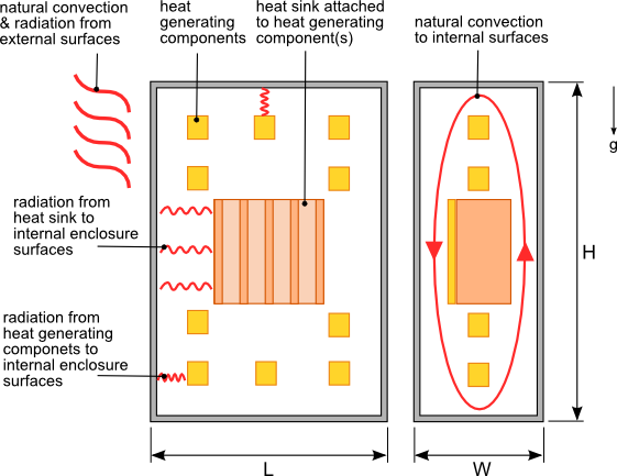
Figure 1. Heat sink housed in a sealed enclosure
Figure 1 shows a heat sink in a sealed enclosure with the heat transfer modes identified. The heat sink is oriented vertically in the enclosure as shown in figure 1. The heat generating components are assumed to be dispersed evenly through out the enclosure so that there are no areas where the air temperature varies widely from the average.
Figure 2 shows the thermal resistance network that represents the heat flow paths from the heat sink and other heat sources in the enclosure to the internal surfaces of the enclosure, through the enclosure walls and then from the external enclosure surfaces to the atmosphere. The section of the thermal resistance network highlighted in figure 2 is identical to that used in the blog post How to calculate the temperature rise in a sealed enclosure. Refer to that blog article for an explanation of the calculation methodology and the equations associated with the thermal resistances in that network.
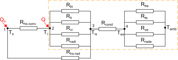
Figure 2. Thermal resistance network of a heat sink in a sealed enclosure
The heat generated by the heat source which is cooled by the heat sink is Qs. The sum of the heat generated by all the other components in the enclosure is Q.
The component thermal resistances of the total heat sink thermal resistance are:
Rhs-conv, is the thermal resistance due to convection from the heat sink to the air inside the enclosure.

where:


The variable 


Reference equation 12 for the definition of hhs-rad.


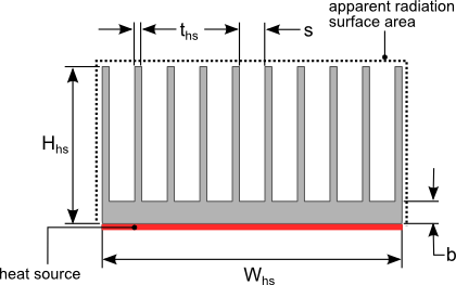
Figure 3. Heat sink dimensions
The calculation of hhs-conv is based on the correlation for natural convection flow through heated vertical parallel plates at a constant temperature [1]. The fins of the heat sink can be approximated as parallel plates. Note that the convection coefficient h for flow on the external surfaces of the heat sink will typically be larger than the value calculated using equation 3. Since the external area is usually much smaller than the total surface area of the heat sink using the convection coefficient calculated in equation 3 for the entire surface area of the heat sink should not impact the accuracy significantly.
This calculation is for a heat source that is the same size as the base of the heat sink, therefore no spreading resistance is included in the calculation. Reference the blog post How to design a flat plate heat sink to learn about how to calculate the thermal spreading resistance. The thermal spreading resistance should be accounted for if the heat source is smaller that the base of the heat sink. Also no contact or junction resistance is included in this calculation.
Rhs-rad, is the thermal resistance due to radiation from the heat sink to the internal surfaces of the enclosure.

Because of the detailed calculation of radiation heat transfer from the heat sink to the internal surfaces of the enclosure are quite complicated and extremely lengthy, an apparent radiation surface area of the heat sink will be used. Imagine the heat sink to be a solid block with the same external dimensions. The apparent surface area is the external surface area of this block excluding the area where the heat source is attached. The apparent surface area is calculated using equation 11.


Reference the blog article How to calculate the temperature rise in a sealed enclosure for the definition of Aend and Avert as well as the equations that define the thermal resistances associated with the enclosure surfaces.
With all of the thermal resistances defined the next step is to solve for the temperatures Ts, Ti the internal average enclosure air temperature, Tis the enclosure internal surface temperature and Tes the enclosure external surface temperature. The conservation of energy principle states that the sum of heat flow (energy) into and out of each node shall be equal to zero. Writing an equation for each node that satisfies the conservation of energy results in the following equations.
Node 1

Node 2


Node 3

Node 4


In order to solve for the unknown temperatures at nodes 1 through 4 equations 14,15, 16 and 17 have to be solved simultaneously using a numerical solver. The Solver addin available in MSExcel can be used to calculate a solution. Equation solving software such as Matlab, MathCAD or Mathematica provide similar numerical solving capability.
[1] F. Incropera, D. DeWitt, (2011). Fundamentals of Heat and Mass Transfer (7th ed.). Hoboken: Wiley.