27 Jul

The importance of radiation in heat sink design

Often times the role radiation plays in the design of a heat sink is overlooked. There are many references that state a percentage value for the heat dissipated from a heat sink. As with most phenomena in physics and engineering the effect of radiation cannot be generalized with one constant number.

There are several factors that determine the influence of radiation on the performance of a heat sink. Before investigating those factors a brief description of radiation is necessary.

Thermal radiation is electromagnetic waves emitted from all matter that has a temperature above 0 Kelvin (absolute zero). The maximum heat (Watts) that can be emitted from a surface due to radiation is given by:

Latex formula1

where:
Latex formula is the surface area of the radiating surface
Latex formula (Stefan-Boltzman constant)
Latex formula is the surface temperature in Kelvin
continue>>

05 Jun

Sizing heat sinks using a few simple equations

Heat sink size calculations can be daunting tasks for any one who does not have much experience in thermal analysis. There are commercially available heat sink design software that would allow you to design and analyze a heat sink to meet the thermal requirements of the device(s) to be cooled. If that type of software is not available to you some quick calculations using a spreadsheet or mathematical software can be done to get an estimate of the heat sink size required to maintain the desired temperature of your components.

Heat sink design assumptions

By making a few simplifying assumptions you can conduct the heat sink analysis by hand or using a spreadsheet. The output of these calculations will be the dimensions of the heat sink required to maintain the required source temperature.

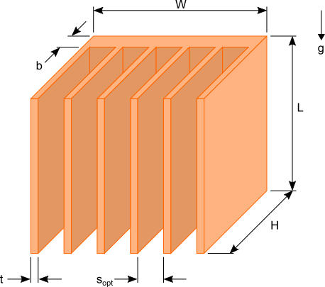
Figure 1. Plate fin heat sink dimensions

Figure 1 shows a typical plate fin heat sink used to cool common electrical / electronic components such as LEDs used in lighting applications and MOSFET used in digital circuits and microprocessors. There are six dimensions that would need to be determined to design an appropriate heat sink for your needs. In order to reduce the complexity of the calculations the following assumptions will be made:
continue>>

04 Sep

Estimating Forced Convection Cooled Heat Sink Performance in a Ventilated Enclosure (Part 2)

The HeatSinkCalculator includes an option to input a fan curve of the fan used to cool the heat sink. This option can be exploited to allow the simulation of the heat sink and fan in a ventilated enclosure as was outlined in part 1 of this article.

It is assumed that the readers of this article already reviewed part 1. Recall from the previous article equation 1 that defines the total pressure difference around the flow network loop.

Latex formula                 (1)

The pressure differences across the fan and two ventilation openings can be summed to create a single parameter ΔPfan* that defines the total pressure difference across all three components.  The parameter ΔPfan* represents the modified fan curve.  This calculation is carried out at the specified volumetric flow rate of each point on the fan curve to generate the modified fan curve. Equation 1 is now reduced to equation 2. Please note that the pressure difference across the fan is considered positive since the pressure increases along the direction of the flow and the pressure difference across the ventilation opening is negative because there is a pressure decrease along the direction of flow.
continue>>

31 Aug

Estimating Forced Convection Cooled Heat Sink Performance in a Ventilated Enclosure (Part 1)

There are many situations in which the heat sink and the device(s) it is cooling are located in an enclosure with ventilation openings. The ventilation openings will allow the inlet of air at the outside ambient temperature and the exit of heated air. When the heat sink is being cooled by forced convection using a fan or blower the size and configuration of the ventilation openings can negatively impact the ability of fan/heat sink to cool the power generating devices when compared to the same fan/heat sink combination located in an open environment outside of the enclosure. This is because the ventilation openings which are typically perforated plates, louvered openings or mesh screens restrict the flow of air. Understanding what impact this restriction has on the volumetric flow rate of the air through the heat sink will allow you to select a heat sink and fan combination to meet the thermal requirements of the device being cooled.

Shown in figure 1 is an enclosure with ventilation openings at both ends. There is a heat sink inside the enclosure with a fan mounted on or very close to the heat sink such that it can be assumed that all of the air flow from the fan will pass through the heat sink.

heat_sink_in_enclosureFigure1.  Heat sink and fan in a ventilated enclosure
continue>>

30 Jul

Validation of the Calculator Results (Natural Convection)

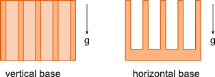
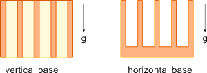
During the development for the Heat Sink Calculator the values calculated for a heat sink cooled via natural convection and radiation were compared against experimental data from work done by Yazicioglu [1] and Kharche et al [2]. The orientations of the base of the heat sinks investigated are shown below.

heatSinkOrientation

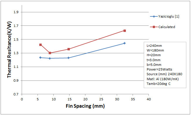
The experimental data for heat sinks under going natural convection/radiation with the base in the vertical orientation is provided by Yazicioglu [1] . The graph below shows a comparison of the experimental data from Yazicioglu [1] with results obtained from the Heat Sink Calculator for various fin spacings.

vertical_nc_comparison
continue>>

18 Apr

Validation of the Calculator Results (Forced Convection)

The Heat Sink Calculator uses a combination of semi-empirically derived equations to calculate the heat transfer and pressure drop due to forced convection. Equations for laminar [1] and turbulent [2] flow are combined to form a single equation that is suitable for calculating the convection coefficient for laminar, transition to turbulent and turbulent flows through the heat sink. Similarly the pressure drop is calculated using laminar and turbulent flow correlations developed by Shah and London [3] and Zhi-Qing [4] respectively.

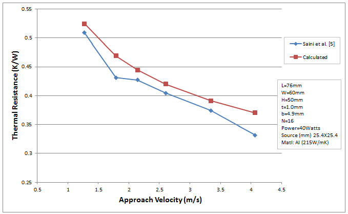
The results obtained from the Heat Sink Calculator have been compared with experimental data that span the laminar and turbulent flow regimes. The graphs below show experimental and calculated data for heat sinks undergoing forced convection. The experimental data are obtained from work done by Saini et al. [5] and Jonsson et al. [6].

thermal_resistance comparison_2
continue>>

03 Mar

Analysis of Heat Sinks Oriented Horizontally

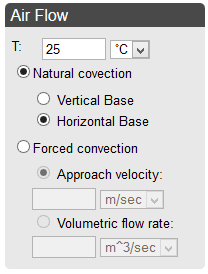
Up until now HeatSinkCalculator has only provided the option to analyze heat sinks under going natural convection with the base oriented vertically. Today we have added the option to perform an analysis when the base is oriented horizontally. There are many design situations where it is preferable or even necessary to orient the heat sink horizontally.

Air_Flow_Input

heatSinkOrientation_blog_post3
continue>>