A heat sink is a part that conducts heat from a heat generating component to a larger surface area to dissipate the heat to the surroundings thus reducing the temperature of the component. Based on this definition anything from a rectangular sheet of metal to a complex finned copper or aluminum extrusion can be used as a heat sink. In situations where there is ample space and/or the heat dissipated by the component is low an aluminum or copper plate can be used as an effective heat sink. The heat sink can be a simple plate or the metal wall of the enclosure housing the component as shown in figure 1.
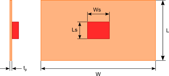 Figure 1. Flat plate heat sink dimensions
To estimate the dimensions of the flat plate heat sink you need to determine the path of heat flowing to the surroundings and the magnitude to which that path resists the flow of heat. The thermal resistance circuit shown in figure 2 will be used to represent the path of heat flow. Let’s examine each of the thermal resistance elements:
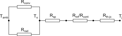
Figure 2. Thermal resistance circuit of a flat plate heat sink
Junction to case resistance
The junction to case thermal resistance (Rth-jc) is the thermal resistance from the operating portion of a semiconductor device to the outside surface of the package (case) where the heat sink will be attached. The case temperature is considered to be at a constant temperature across the attachment surface. Rth-jc is a measured value typically provided by the device manufacturers and specified in the data sheet for the device.
Contact and thermal Interface resistance
The thermal contact resistance (Rcont) is the thermal resistance between the case and the heat sink. Because of imperfections in the surface of the case and heat sink the actual contact area is smaller than the apparent contact area as shown in figure 3. Mathematical models have been proposed to calculate Rcont that are based on the contact pressure, material surface roughness and material hardness. These models can be quite complicated and the material surface and hardness information may be difficult to obtain. Typically Rcont is determined based on experimental data and past experience.
In order to reduce the influence of Rcont interface materials that fill the gaps between the case and the heat sink are used. These materials come in the form of special thermal greases, filler compounds, phase changing thermal pads and thermal tapes. The thermal conductivity of these materials range between 0.5 W/m-K to 4 W/m-K. With the gap between the two mating surfaces filled with the thermal interface material the thermal resistance across the case and the heat sink is now a function of the interface material thickness, thermal conductivity and surface area given by equation 1.

where:


Note for many thermal interface materials the thermal conductivity varies with clamping pressure. The manufacturer will typically provide these data in the product specification sheets.

Figure 3. Contact, interface and junction to case resistances
Thermal spreading resistance
The thermal spreading resistance (Rsp) is a result of heat flowing via conduction between the contact area of the case on the surface of the flat plate and the larger heat dissipating surface area of the flat plate. Closed form equations for Rsp were develop by Lee et al [1]. These equations provide a very close approximation to the exact solution which will not be discussed here because of the complexity of the calculations required.
The first step in using Lee’s equations is to convert the dimensions of the two interacting rectangular surfaces into equivalent radii using equations 2 and 3.


Rsp can then be calculated using the following equations:


where:

See equation 18 for the calculation of heff.


Convection thermal resistance
The convection thermal resistance factors in how well heat is removed from the surface of the plate via the movement of air. The dimensionless Nusselt number [2] for a heated vertical flat plate undergoing natural convection is given by equation 11. The Nusselt number is a dimensionless variable used in convection calculations.

where:


The average convection coefficient is calculated with equation 14. The convection thermal resistance Rconv is a function of the plate surface area Ap and the average convection coefficient and is calculated using equation 15. Note the plate surface area does not include the area resulting from the plate thickness since this is considered much much smaller than the front and back surface areas.

where:


Radiation thermal resistance
The thermal resistance due to radiation is given by equation 16.

where:


It is assumed that the plate is radiating heat to a much larger surrounding surface as such the surroundings can be considered an ideal radiator or blackbody. In certain situations, the temperature of the surrounding surface may be different than the ambient air temperature. In these cases, Tamb should be replaced with the temperature of the surrounding surface in equation 15.
The effective convection coefficient heff used to calculate the thermal spreading resistance is given by equation 18.

The values of Rrad, Rconv and Rsp cannot be directly solved for since they are functions of Ts the surface temperature of the plate. Assuming that all the heat generated by the heat source is being dissipated by the flat plate the equation defining this energy balance is given by equation 19.

where:

Ts can be calculated using a numerical solver available in most mathematical software or the “Goal Seek” function in Excel.
With all the thermal resistances known the thermal circuit shown in figure 2 can be reduced to a single junction to ambient resistance Rj-a using equation 20.

Finally using equation 21 the junction or heat source temperature can be obtained.

An online heat sink calculator based on the calculation methodology described in this blog post is available free of cost. Click the following link to access the calculator: Flat Plate Heat Sink Calculator
References:
[1] S. Lee, S. Song, V. Au, and K.P. Moran, “Constriction/Spreading Resistance Model for Electronic Packaging,” in: Proceedings of ASME/JSME Engineering Conference, Vol. 4, 1995
[2] F. Incropera, D. DeWitt, (1990). Fundamentals of Heat and Mass Transfer (3rd ed.). Hoboken: Wiley. pp. 542
