Often times the role radiation plays in the design of a heat sink is overlooked. There are many references that state a percentage value for the heat dissipated from a heat sink. As with most phenomena in physics and engineering the effect of radiation cannot be generalized with one constant number.
There are several factors that determine the influence of radiation on the performance of a heat sink. Before investigating those factors a brief description of radiation is necessary.
Thermal radiation is electromagnetic waves emitted from all matter that has a temperature above 0 Kelvin (absolute zero). The maximum heat (Watts) that can be emitted from a surface due to radiation is given by:

where:


This surface is considered an ideal radiator or blackbody. Surfaces that are not an ideal radiator radiate less energy than a blackbody at the same temperature. These surfaces are given a radiative property 
| Surface Material | Emissivity |
| Extruded Aluminum | 0.09 |
| Anodized Aluminum | 0.85 |
| Unfinished Aluminum Plate | 0.09 |
| Copper, commercial burnished | 0.07 |
| Copper Polished | 0.03 |
| Oil Paints, (various colors) | 0.90-0.96 |
Table 1. Emissivities of common heat sink materials and surface finishes
When two or more surfaces are involved, radiant energy is absorbed and emitted by each surface. One of simplest forms of radiation exchange is in the case of a surface in a much larger enclosure. The surface is at a higher temperature than the enclosure, with a surface area A and emissivity
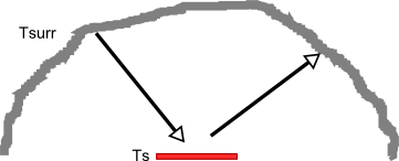 Figure 1. Radiation exchange between a small heated surface and the inside of a large enclosure
Because a heat sink consists of several surfaces that absorb and emitted radiation to each other and the enclosure, the equations that represent those interactions are not as straight forward as equation 1. However the general principle represented in equation 1 still apply. A thorough explanation of the radiation calculations and corresponding equations for a plate fin heat sink can be found in [1].

The calculations in [1] require the use of several equations and can be tedious to work through. To get a reasonable estimate of heat loss due to radiation from your plate fin heat sink equation 2 can still be used by calculating an apparent radiation surface area. The apparent radiation surface area is calculated by assuming the heat sink is a solid block with the same external dimensions. The surface area of that block as shown in figure 2 is then calculated using equation 3 and used in equation 2. This calculation method does not account for the variation in temperature between the base of the heat sink and tip of the fins which may be significant in forced convection, with long fins, heat sinks made from low conductivity material or a combination of these. Additionally the use of the apparent radiation surface area does not accurately account for the surface area of the fins. As such this method should not be used if very accurate results are needed.

where:

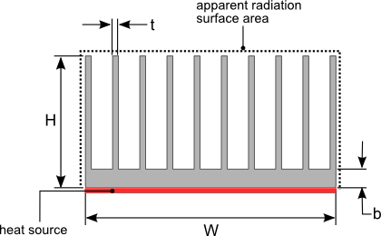 Figure 2. Heat sink dimensions
The heat (power) dissipation from a heat sink to its surroundings is by two means, radiation and convection. The heat dissipation due to convection is given by equation 4.

where:

is the ambient air temperature

Values for the convection coefficient h in air range from 2 to 10 W/m2K for natural convection and 20 to 100 W/m2K for forced convection with a fan. Because of the significantly higher values of h for forced convection, convection generally accounts for a much larger percentage of the heat dissipated from a heat sink than radiation under forced convection. This statement generally holds true when the heat sink is at temperatures lower than 150°C the typical temperature range at which heat sinks used to cool electrical and electronic components operate. The heat dissipated via radiation is strongly dependent on temperature of the heat sink sink since it’s raised to the forth power as seen in equations 1 and 2.
To provide a comparison of the influence of radiation on the performance of a plate fin heat sink two examples were analyzed using the HeatSinkCalculator. The first is a heat sink cooled via forced convection. The heat source covers the entire base of the heat sink as shown in figure 2. The air flow is through the heat sink fins is parallel to the fins and base of the heat sink. All the air flow passes through the fins of the heat sink with no air bypass. The results of the analysis at various power inputs are presented in table 2. The dimensions and heat sink material are listed below along with the flow rate through the heat sink.
L[mm]:50.8
W[mm]:50.8
b[mm]:5.5
t[mm]:0.89
Number of fins:15
Material:6063-T6 [209W/(mK)]
Flow rate[CFM]:6.9
Ambient Temperature[°C]:30
| Qsource [W] | Emissivity | Tsource [°C] | %Qconv | %Qrad |
| 100 | 0.85 | 72.2 | 96.1% | 3.9% |
| 140 | 0.85 | 114 | 95.4% | 4.6% |
| 190 | 0.85 | 143 | 94.7% | 5.3% |
| 175 | 0.07 | 147 | 98.3% | 1.7% |
Table 2. Forced convection heat sink results
As expected the percentage of heat dissipated via radiation increases as the temperature of the heat sink increases. At higher temperatures the heat dissipated via radiation is over 5% of the total. In certain critical situations this may mean the difference between meeting or not meeting the temperature rating of the component being cooled.
The second example is of a heat sink cooled via natural convection with base of the heat sink and heat sink fins oriented vertically. As with the previous example the heat source covers the entire base of the heat sink as shown in figure 2. The dimensions and heat sink material are listed below. Table 3 shows the results of this analysis at various power inputs and surface emissivities.
L[mm]:50
W[mm]:45.6
b[mm]:4.3
t[mm]:1.2
Number of fins:8
Material:6063-T6 [209W/(mK)]
Ambient Temperature[°C]:30
| Qsource [W] | Emissivity | Tsource [°C] | %Qconv | %Qrad |
| 5 | 0.85 | 61.8 | 69.6% | 30.4% |
| 15 | 0.85 | 104 | 71.3% | 28.3% |
| 25 | 0.85 | 141 | 69.6% | 30.4% |
| 25 | 0.09 | 168 | 90.2% | 9.8% |
Table 3. Natural convection heat sink results
The percentage of heat dissipated via radiation is significantly higher in natural convection. In the example presented the percent radiation dissipation is close to or above 30%. The rate of heat loss via natural convection is also highly dependent on the surface temperature of the heat sink. This explains the rise in percent radiation dissipation with a decrease in source temperature. When the surface emissivity is reduced to 0.09 the impact to the heat sink temperature is almost 30°C.
The examples presented highlight the importance of radiation in the cooling of a heat sink. Although radiation has a smaller impact on cooling a heat sink in forced convection its effects can still be relevant if a few extra degrees are need to ensure that the product meets the specification. It is evident that the role of radiation for a heat sink cooled via natural convection is extremely important. Significant decreases in temperature can be achieved by simply modifying the heat sink surface by anodizing or painting to increase the value of the surface emissivity.
[1] Y. Shabany “Radiation Heat Transfer from Plate-Fin Heat Sinks”, in: Proceedings of 24th Semiconductor Thermal Measurement and Management Symposium, 2008. (Semi-Therm 2008), pp. 132-136
