Heat sink size calculations can be daunting tasks for any one who does not have much experience in thermal analysis. There are commercially available heat sink design software that would allow you to design and analyze a heat sink to meet the thermal requirements of the device(s) to be cooled. If that type of software is not available to you some quick calculations using a spreadsheet or mathematical software can be done to get an estimate of the heat sink size required to maintain the desired temperature of your components.
Heat sink design assumptions
By making a few simplifying assumptions you can conduct the heat sink analysis by hand or using a spreadsheet. The output of these calculations will be the dimensions of the heat sink required to maintain the required source temperature.
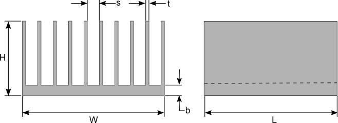
Figure 1. Plate fin heat sink dimensions
Figure 1 shows a typical plate fin heat sink used to cool common electrical / electronic components such as LEDs used in lighting applications and MOSFET used in digital circuits and microprocessors. There are six dimensions that would need to be determined to design an appropriate heat sink for your needs. In order to reduce the complexity of the calculations the following assumptions will be made:
- The surface area due to the thickness of the fins t, and thickness of the base b are much much smaller than the total surface area of the heat sink
- The thermal conductivity of the heat sink is high enough so that the temperature of the surface of heat sink is uniform and approximately equal to the temperature of the heat source
- The heat source has the same length and width of the heat sink and is centered on the base of the heat sink
- The heat source is in perfect contact with the base of the heat sink
The above assumptions will introduce some errors in your calculations. However, the purpose of conducting this calculation is to get a rough estimate of the size of the required heat sink. More sophisticated calculation methods, software or testing can then be used to refine the design.
This analysis is for a heat sink whose base is oriented vertically utilizing via natural convection and radiation only as shown in figure 1.
Natural convection calculations
Values for L and H are first chosen based on your heat sink design constraints. The width, W of the heat sink, spacing between the fins, s and number of fins, N will then be calculated for the selected values of L and H.
The convection heat dissipation, Qc1 from area A1 the external side surfaces of the heat sink shown figure 2 is first calculated. This is determined using equation 1.

where:


The convection coefficient, h1 for the area A1 is calculated using equation 3. This formula is for natural convection from a vertical surface. See reference [2] for details regarding the development of this formula. The area A1 includes small areas of horizontal surfaces. The difference in magnitude of the natural convection coefficient for horizontal and vertical surfaces is not significant and the horizontal areas are small relative to the vertical surfaces. As such utilization of equation 3 for this entire area will not introduce significant error and will simplify the calculation.

The next step in the calculation is to determine the heat dissipation, Qc2 due to natural convection from surface area, A2 of the fins as shown in figure 2.

The optimum spacing between the fins, sopt that produces the maximum heat transfer due to natural convection is given by equation 5. Equation 5 was derived by calculating the fin spacing at which the product of the internal surface area of the fins and the convection heat transfer coefficient is maximized. A detailed explanation of this derivation can be found in [1].

where:


The convection heat transfer coefficient between the fins [1] is given by equation 7,

where 

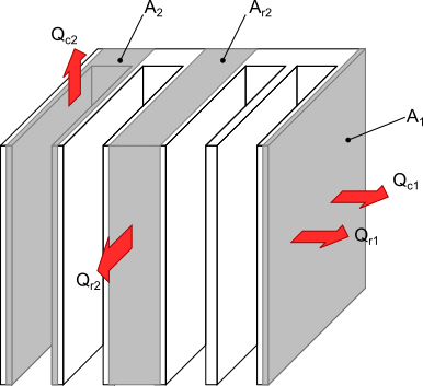
Figure 2. Areas used to calculate the heat dissipation from the heat sink
The heat dissipation Qc2 from area A2 due to natural convection is calculated using equation 8.

The convection coefficient h2 is for the vertical surfaces located between the fins. This convection coefficient is used for the small horizontal surfaces as well as the small vertical surfaces on the outside of the heat sink that are included in the area A2. As was done in the calculation for Qc1 the use of a single value of h2 over the area A2 is considered acceptable because of the small areas of the horizontal and external vertical surfaces and the similar magnitudes of the convection coefficient for surfaces in different orientations.
Radiation calculations
The contribution of radiation heat dissipation can be quite significant for natural convection cooled heat sinks. As such it must be included in any heat sink size calculations. Reference the blog post The importance of radiation in heat sink design for a detail review of the role radiation plays in heat sink performance.
As with the natural convection heat sink calculations, the radiation heat dissipation Qr1 from the area A1 is calculated using equation 9.

The variable ε is the surface emissivity of the heat sink. Typical values are listed in the article The importance of radiation in heat sink design. The Stefan-Boltzmann constant σ has a value of 5.67×10⁻⁸ W/m2K4.
Next, the radiation heat transfer from the area A2 given by equation 10 is calculated.

The calculation of the exact radiation heat dissipation from area, A2 is quite involved and is not suitable for the simplified solution sought in this article. An approximate solution that produces reasonably accurate results is to use an apparent radiation surface area, Ar2. The apparent radiation surface area is an imaginary area that covers the envelop of the heat sink encompassing the area A2 illustrated in figure 2.

Heat sink calculations
The final step is to now calculate the number of fins, N needed to dissipate the heat at the temperature Ts. With the number of fins known the width of the heat sink can then be calculated.
The law of conservation of energy dictates that the heat generated by the heat source, Q must be equal to the heat dissipated by the heat sink under steady state conditions. This is represented by equation 12.

The ⌈ ⌉ notation used in equation 12 is the mathematical notation for rounding up to the nearest integer. This is needed since the number of fins is an integer. Equation 13 is used to determine the width of the heat sink.

These calculations provide some insight into what dimensions should be varied to optimize the size of the heat sink. If you are trying to minimize the volume of the heat sink the length should be made a small as possible. This will maximize the heat transfer from the heat sink as such reducing the surface area required to limit the source temperature below the required value.
An online heat sink size calculator that uses the calculation procedure outlined in this blog post is available free of cost. Click the following link: Heat Sink Size Calculator Software
Check out our post Heat Sink Design Optimization for Forced Convection for an explanation of the calculations used for optimizing and sizing heat sinks cooled via forced convection.
References:
[1] A. Bar-Cohen, W. M. Rohsenow “Thermally Optimum Spacing of Vertical, Natural Convection Cooled, Parallel Plates”, in: Journal of Heat Transfer, Vol 106, p. 116-123, 1984
[2] R Simons, “Simplified Formula for Estimating Natural Convection Heat Transfer Coefficient on a Flat Plate”, in: Electronics Cooling, Issue: August 2001
