The HeatSinkCalculator includes an option to input a fan curve of the fan used to cool the heat sink. This option can be exploited to allow the simulation of the heat sink and fan in a ventilated enclosure as was outlined in part 1 of this article.
It is assumed that the readers of this article already reviewed part 1. Recall from the previous article equation 1 that defines the total pressure difference around the flow network loop.

The pressure differences across the fan and two ventilation openings can be summed to create a single parameter ΔPfan* that defines the total pressure difference across all three components. The parameter ΔPfan* represents the modified fan curve. This calculation is carried out at the specified volumetric flow rate of each point on the fan curve to generate the modified fan curve. Equation 1 is now reduced to equation 2. Please note that the pressure difference across the fan is considered positive since the pressure increases along the direction of the flow and the pressure difference across the ventilation opening is negative because there is a pressure decrease along the direction of flow.

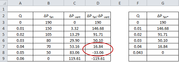
Figure 1. Modified fan curve calculation in MSExcel
Figure 1 shows an example of the calculation carried out using MSExcel. The values of ΔPfan-ΔPvent decrease until eventually the values turn negative. In order to create the modified fan curve the value of Q at which ΔPfan-ΔPvent=0 must be determined. This point lies between the two data points circled in red in Figure 1. To calculate this value of Q we will assume that the function is linear between each data point. The INTERCEPT function in MSExcel is used to estimate the value of Q when ΔPfan-ΔPvent=0. The INTERCEPT function takes two y points and two x points that lie on a straight line and calculates the point at which the line intersects the y-axis. The function INTERCEPT(A7:A8,D7:D8) is entered in cell F8 to calculate the value of Q at ΔPfan-ΔPvent=0. The values of Q and ΔPfan* are entered as the modified fan curve data.
Shown in figure 2 is a graph of the data shown in table 1. The addition of the pressure drops across the ventilation openings reduces the pressure difference across the fan at the same volumetric flow rate.
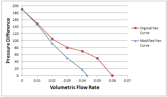
Figure 2. Graph of pressure difference versus volumetric flow rate for the original and modified fan curves
