There are many situations in which the heat sink and the device(s) it is cooling are located in an enclosure with ventilation openings. The ventilation openings will allow the inlet of air at the outside ambient temperature and the exit of heated air. When the heat sink is being cooled by forced convection using a fan or blower the size and configuration of the ventilation openings can negatively impact the ability of fan/heat sink to cool the power generating devices when compared to the same fan/heat sink combination located in an open environment outside of the enclosure. This is because the ventilation openings which are typically perforated plates, louvered openings or mesh screens restrict the flow of air. Understanding what impact this restriction has on the volumetric flow rate of the air through the heat sink will allow you to select a heat sink and fan combination to meet the thermal requirements of the device being cooled.
Shown in figure 1 is an enclosure with ventilation openings at both ends. There is a heat sink inside the enclosure with a fan mounted on or very close to the heat sink such that it can be assumed that all of the air flow from the fan will pass through the heat sink.
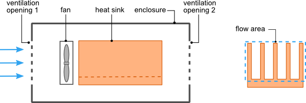 Figure1. Heat sink and fan in a ventilated enclosure
As the air flows through the ventilation openings and the heat sink there is a drop in pressure across each component. In order analyze the flow through the enclosure we will apply rules which are analogous to the analysis of an electric circuit. Figure 2 shows the network representation of the flow through the enclosure. The pressure source Pfan represents the pressure increase created by the fan, Rvent1, Rvent2 and Rhs are the flow resistances of the ventilation openings and heat sink respectively. The fan is analogous to a voltage source and flow resistances analogous to electrical resistances in an electric circuit.
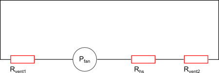 Figure2. Flow network
The sum of the pressure differences around the flow network loop must be equal to zero.

For a detailed explanation of how the pressure drop across a heat sink based on rate flow rate is calculated refer to the post Heat Sink Design Optimization for Forced Convection.
The variation of pressure across the fan as a function of the volumetric flow rate can be obtained from the fan flow curve provided by the fan manufacturer. The flow curve will be provided as a graph or data points of pressure difference across the fan versus volumetric flow rate.
To calculate the pressure drop across the ventilation openings equations obtained from Idelchik [1] are used. The equation show below for 
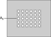 Figure 3. Ventilation openings


Note: 

The pressure drop across the ventilation openings is given by

where:


for Re>10^5

for 30<Re<10^5

for Re<10


where:

The values for 


We wish to calculate the volume flow rate Q so that can be used to calculate the thermal resistance of the heat sink and the temperature of the device being cooled. This is done by substituting the pressure drop across the ventilation openings, the appropriate equation of the pressure drop across the heat sink and a linearized form of the fan curve data into equation for the sum pressure differences around the flow network loop and solving for Q. This can done with MSExcel, MathCad or using some other numerical solver.
In part 2 of this article an explanation of how a modified fan curve can be used in the HeatSinkCalculator to analyze a heat sink within a ventilated enclosure will be presented.
References:
[1] I.E. Idelchik, “Handbook of Hydraulic Resistance, 2nd edition”, Hemisphere Publishing Corporation, New York NY
[2] J.R. Culham, Y.S. Muzychka “Optimization of Plate Fin Heat Sinks Using Entropy Generation Minimization”, in: IEEE Transactions on Components and Packaging Technology, Vol 24, No.2, pp. 34-41, 2001
