The optimum design of heat sinks particularly in high heat load devices such as MOSFETs and IGBTs is essential for the efficient operation of these devices and to avoid premature part failure. The use of fans in combination with heat sinks are required to provide adequate cooling for high power devices with significant heat dissipation.
A shroud or duct is often used to channel the airflow from the fan into the heat sink as shown in figure 1 to prevent any bypass of airflow around the heat sink which would decrease the effective cooling capacity of the fan and heat sink combination.
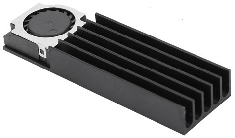
Figure 1 Heat sink and blower fan with no bypass flow
A straightforward calculation of the optimum fin spacing, and the resulting thermal resistance of the fan/heat sink combination shown in figure 1 can be conducted with a few equations allowing for a quick estimation of the heat sink size required for your application.
Note: The optimization of the fin spacing of a heat sink that has an assumed constant approach velocity or volume flow rate is not feasible. The velocity of the air flow between the fins is determined by the fin spacing and number of fins using equation 1. This formula states that the volume flow rate of the air approaching the heat sink is the same as the volume flow rate of the air passing through the heat sink since there is no flow bypass around the heat sink.
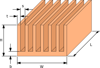
Figure 2. Fan cooled heat sink dimensions

where: 


The smaller the fin spacing, s the higher the velocity of air, Vf flowing between the fins. The higher the air velocity the more effective the cooling of the fins. If you were to try to optimize the heat sink dimensions the spacing between the fins would be a very small value since the air velocity and hence rate of cooling increases with decreasing fin spacing. In real world applications the flow is supplied by a fan or blower. The flow rate would not be fixed, it would be limited by the increase in pressure drop across the heat sink that would occur as the spacing between the fins, s decreases.
Heat sink design assumptions
To simplify the analysis without introducing significant calculation errors the following assumptions will be made.
- The surface area due to the thickness of the fins t, and thickness of the base b are much smaller than the total surface area of the heat sink.
- The heat source has the same length and width of the heat sink and is centered on the base of the heat sink.
- The heat source is in perfect contact with the base of the heat sink
- All the flow from the fan or blower passes through the heat sink.
- Heat transfer due to radiation is small compared to that due to convection and can be ignored.
- The flow through the heat sink is laminar and steady.
- The thickness of the fins is small in comparison to the spacing, s between the fins
The assumption of laminar flow through the heat sink holds true for a large majority of commercial heat sink/fan combinations. Fan noise is a major consideration in electronics products as such fan speeds are intentionally kept lower to avoid significantly increasing the noise level which can occur as the flow transitions from laminar to turbulent.
Calculating the fan flow rate
The first step in designing a heat sink is to determine the operating point of the fan and heat sink combination. When a fan or blower is paired with a heat sink the performance of the fan will depend on the design of the heat sink.
Every fan has a unique pressure/flow rate performance curve in which the flow rate is inversely proportional to the pressure drop across the fan as shown in figure 3. Heat sinks also have a pressure/flow rate performance curve that is proportional to the pressure drop across the heat sink also shown in figure 3. The resulting flow rate through a fan/heat sink combination is the intersection of the fan and heat sink pressure/flow rate curves.
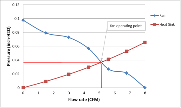
Figure 3. Fan and heat sink pressure versus flow rate curves
The fan curves are typically provided by the fan manufacturer and are often quite non-linear. In many instances the only fan performance data provided is the maximum flow rate and the maximum pressure drop. To simplify the calculation of the flow rate and accommodate instances where only the maximum flow rate and the maximum pressure drop are provided for the fan, a simple linear approximation of the fan curve can be expressed with equation 2. This linear approximation of the fan curve in most cases provides a reasonable estimate of the fan performance curve.

where: 

In situations where multiple fans are used side by side (in parallel) the maximum flow rate of the fans, Vmax is the maximum flow rate of one fan times the number of fans.
The equation for the pressure drop across the heat sink is given by equation 3.

The density of the air ρ is calculated the at the ambient air temperature.
The hydraulic diameter of the passage between the fins Dh can be approximated as 2s. The variables Kc and Ke are the pressure loss coefficients due to the constriction and expansion respectively of the air as the flow enters and exits the heat sink. Equations for these pressure loss coefficients are a function of the frontal area σ=s/(s + t) and are based on graphs provided in reference 1.


The apparent friction factor fapp is based on a model developed in reference [2].


The 

To determine the operating point of the fan/heat sink (i.e., the intersection of the fan and heat sink pressure/flow rate performance curves) equation 2 and 3 are equated and the unknown variable

Optimizing the fin spacing
The spacing between the fins that provides the maximum rate of heat transfer, sopt is calculated using equation 9 in which μ and α are the viscosity and thermal diffusivity of air respectively. This equation was developed by Bejan et al in reference 3.

The optimum fin spacing, sopt is a function of the pressure drop across the fan, ΔPfan and hence the heat sink, ΔPhs. The pressure across the system determines the flow rate through the heat sink,
Equation 9 is substituted for the fin spacing, s in equation 8 and then the flow rate of the system is determined by solving the resulting equation for
Note that even though ΔPfan and ΔPhs are equal when equation 8 is solved, only equation 2, ΔPfan should be used in equation 9 when solving for
Calculating the heat sink thermal resistance
With the flow rate,
The average heat transfer coefficient, hf from the heat sink fins is calculated using equations 10, 11, 12, 13 and 14, developed in reference 4.

Where k is the thermal conductivity of air and kf is the thermal conductivity of the fins.


Pr is the Prandtl number for air. A value of 0.71 can be used for the typical temperature ranges at which a heat sink used in electronic cooling operates.


The total thermal resistance of the heat sink, Rhs is then:

The thermal conductivity of the heat sink base is kb and the wetted surface area of the heat sink Ahs is the area in contact with the air flowing through the heat sink.
The first term in equation 15 is the thermal resistance due to the fins and term after the plus sign is the thermal resistance due to the base of heat sink.

Check out our post Sizing heat sinks using a few simple equations for an explanation of the calculations used for optimizing and sizing heat sinks cooled via natural convection.
References
[1] W. M. Kays and A. L. London, Compact Heat Exchangers. New York:
McGraw-Hill, 1984
[2] Y. S. Muzychka and M. M. Yovanovich, “Modeling friction factors in
non-circular ducts for developing laminar flow,” in Proceeding of the 2nd AIAA Theoretical Fluid Mechanical Meeting, Albuquerque, NM, June 15–18, 1998
[3] A. Bejan and E. Sciubba, “The optimal spacing of parallel plates cooled by forced convection,” in the International Journal of Heat and Mass Transfer, Vol. 35, No. 12 pp. 3259-3264, 1992
[4] P. M. Teertstra, M. M. Yovanovich, J. R. Culham, and T. F. Lemczyk,
“Analytical forced convection modeling of plate fin heat sinks,” in Proceedings of the
15th Annual IEEE Semiconductor Thermal Measurement and Management Symposium., San Diego, CA, March 9–11, 1999, pp. 34–41
