25 Feb

How to calculate the thermal resistance of a PCB

Thermal management is a crucial aspect of designing and manufacturing electronic devices, as heat generated by the components can lead to performance issues and even device failure. To ensure the reliable and efficient operation of electronic devices it is essential to understand how to effectively dissipate heat away from the heat generating devices.  These heat generating components are often mounted on printed circuit boards (PCBs) which in many cases are used as a heat sink to cool the attached component.

Thermal resistance is a measure of how well a material or device transfers heat to its surroundings and is often used to predict the thermal performance of a PCB and to calculate the temperature of the attached component. This technical article will provide a detailed explanation of the formulas and method used to calculate the thermal resistance of a PCB. The calculation methodology will take into account the PCB insulation (FR4)/copper layer thicknesses, percent copper coverage in each layer, location of these layers with respect to the heat generating component and usage of thermal vias. 


Layout and structure of the PCB

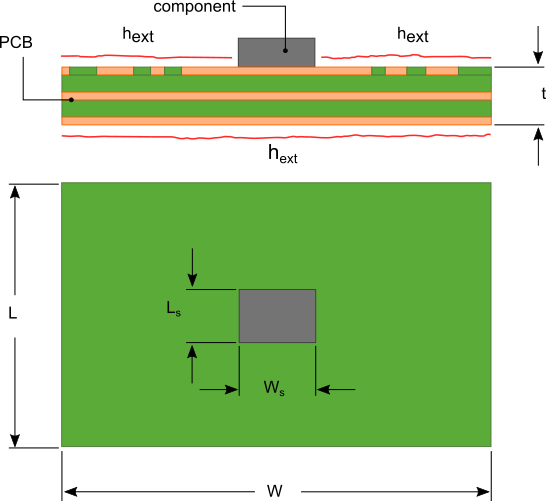
A PCB consists of alternating layers of dielectric and conductive materials typically made using FR4/resin and copper respectively as shown in figure 1.  Layers that are used for ground planes often are 100% conductive material. While the layers with attached components, traces and interconnects will have some mixture of conductive and dielectric materials. 

PCB with attached component cooled via convection


Figure 1. PCB layout

continue>>

17 Oct

Heat Sink Design Optimization for Forced Convection

The optimum design of heat sinks particularly in high heat load devices such as MOSFETs and IGBTs is essential for the efficient operation of these devices and to avoid premature part failure. The use of fans in combination with heat sinks are required to provide adequate cooling for high power devices with significant heat dissipation. 

A shroud or duct is often used to channel the airflow from the fan into the heat sink as shown in figure 1 to prevent any bypass of airflow around the heat sink which would decrease the effective cooling capacity of the fan and heat sink combination.


Heat sink with fan no bypass flow

Figure 1 Heat sink and blower fan with no bypass flow

A straightforward calculation of the optimum fin spacing, and the resulting thermal resistance of the fan/heat sink combination shown in figure 1 can be conducted with a few equations allowing for a quick estimation of the heat sink size required for your application. continue>>

05 Dec

How to calculate the temperature rise of a PCB and its components

Heat generating electronic components mounted to print circuit boards (PCB) often times rely on the PCB to help dissipate heat to keep the component operating below its maximum temperature limit.   Many semi-conductor components are constructed with an exposed metal pad that is directly attached to the PCB to create a low thermal resistance path between the junction of the component and PCB. In this situation the PCB acts as heat sink that conducts heat away from the component and dissipates it to the environment from its large surface area.

Estimating the junction temperature of surface mounted components requires some simplifications to allow the use of manageable calculations that can be carried out using a spreadsheet. The calculation procedure and associated simplifications and assumptions are explained in the following sections.

PCB Effective Thermal Conductivity

Because of the discontinuous distribution of conductor material  used to create traces, ground planes, vias and electrical connection points the thermal conductivity of the PCB is non uniform.  To conduct the thermal calculations required to determine the board and component temperatures a single effective thermal conductivity of the PCB is required. A widely used method for calculating an effective PCB thermal conductivity is to use a weighted volume approach.  The weighted volume effective thermal conductivity is given by equation 1

Latex formula1

where:
Latex formula2
Latex formulais the total conductor volume
Latex formulais the total dielectric volume
Latex formulais the thermal conductivity of the conductor
Latex formulais the thermal conductivity of the dielectric

Often times it may be difficult to determine the values of Vc and Vd. A reasonable estimate of the conductor volume for modern PCBs is between 10% and 20%.

PCB Effective Convection Coefficient

Heat loss from the surface of the PCB takes place due to radiation and convection to the ambient. The following calculations to determine the temperature rise of the PCB components utilize an effective convection coefficient heff that is a sum of the average convection coefficient due to convection and that due to radiation. The correlations used to calculate the convection coefficients from a flat plate due to radiation and convection will be used.

Equations 11 through 18 in the blog post How to design a flat plate heat sink can be used to determine the effective convection coefficient for a PCB oriented vertically that is cooled via natural convection and radiation.

For horizontally oriented PCBs reference equations 1 through 7 in the blog post Performance of a LED flat plate heat sink in multiple orientations to determine the natural convection coefficient. This is added to the radiation convection coefficient which is independent of orientation to determine the overall effective convection coefficient heff.

PCB Temperature Distribution

A PCB from a heat transfer perceptive is a convection cooled flat plate with heat sources distributed across the surface of the plate as shown in figure 1. A method for calculating the temperature distribution across a flat plate that can be implemented using a spreadsheet or common mathematics software is the modified Bessel function method.
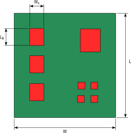
Figure 1. PCB with heat generating components
continue>>

08 Aug

Selecting the best type of heat sink for your application

The need for heat sinks with increased cooling capacity has been driven by the ever increasing heat generation of electronic devices. This has led to the increased manufacture of pin fin heat sinks as shown in figure 1 that vendors claim has vastly superior performance to the traditional plate fin heat sink with continuous parallel fins as shown in figure 2. Is this claim true? Like most engineering answers….it depends.

pin fin heat sinkFigure 1. Pin fin heat sink


The goal of a heat sink is to efficiently remove heat from the source(s) it is attached to so as to minimize the temperature of that source(s). The performance of the heat sink is governed by this simple heat transfer equation:

Latex formula1

where:
Latex formulais the heat from the source(s) being cooled
Latex formulais the convection coefficient of the heat sink
Latex formulais the total surface area of the heat sink
Latex formulais the temperature of the source being cooled
Latex formulais the ambient temperature

Any heat sink with a larger value of h x A will be able to produce a lower source temperature.

plate fin heat sink attached to a PCB

Figure 2. Plate fin heat sink attached to a printed circuit board
continue>>

05 Jul

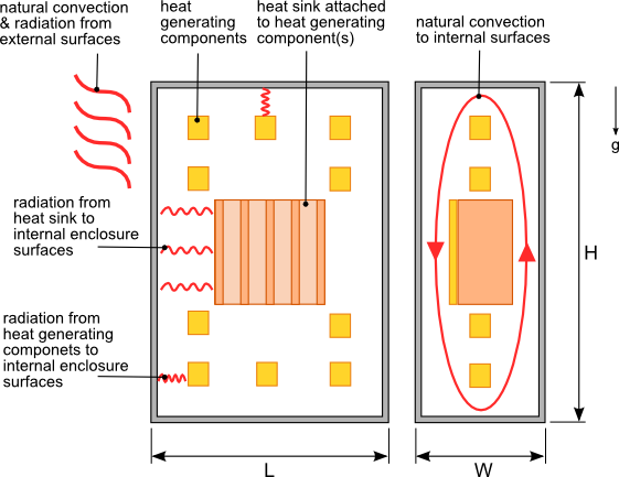
How to Calculate Thermal Resistance of a Heat Sink in an Enclosure

Electrical or electronic components housed in sealed enclosures are especially susceptible to over heating due to the formation of hot spots. Heat sinks may be used on components to provide localized cooling to mitigate the effect of hot spots and/or to provide extra cooling for critical components.

The performance of a heat sink in a sealed enclosure is influenced by the size of the enclosure, proximity of other heat generating components, the ability of air to flow freely through the heat sink and the internal/external surface emissivity of the enclosure.  In order to be able to estimate heat sink performance let’s make some assumptions regarding the enclosure layout and heat sink.

  1. The structures in the enclosure do not significantly obstruct the movement of air flow throughout the enclosure
  2. Air flow through the heat sink is not restricted due to the lack of ventilation in the enclosure
  3. Radiation exchange between other heat generating components and the heat sink is negligible.

If you strongly believe that these assumptions are not valid for your situation then a computational fluid dynamic/finite element  analysis of your design will be your most accurate alternative analysis method.


heat sink in a sealed enclosure

Figure 1. Heat sink  housed in a sealed enclosure
continue>>

30 Aug

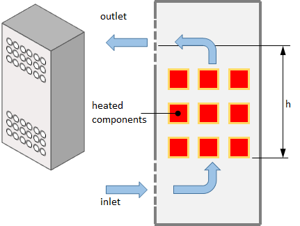
How to calculate the temperature in a ventilated electronics enclosure

Electrical and electronic components are sometimes housed in enclosures with ventilation openings to allow ambient air into the enclosure to more efficiently cool heat generating components. The most common ventilation configuration is to have openings at the top and bottom of the enclosure as shown in figure 1.


ventilated enclosure in natural convection

Figure 1. Ventilated enclosure cooled via natural convection

The air flow through the enclosure is driven by the difference in air density of the cooler air outside the enclosure and warmer air inside due to the heat transferred from the heat generating components. As the air flows vertically through the lower ventilation openings and across the heat generating components its temperature increases. As a result components mounted at higher locations in the enclosure will be subjected to air temperatures above the ambient air temperature. Determining the internal air temperature surrounding these components will allow you to identify and relocate components that have a maximum ambient operating temperature lower than the surrounding air temperature. The size or number of the ventilation openings can also be adjusted to lower the internal ambient temperature.
continue>>

01 Aug

Performance of a LED flat plate heat sink in multiple orientations

Heat sinks are used to cool light emitting diodes (LEDs) in a similar manner to many other semi-conductor devices such as MOSFETs, CPUs and simple diodes. However LEDs because of their varied applications can be installed in various orientations unlike other semi-conductor devices which typically have a fixed orientation. The heat sinks to which LEDs are attached must be able to maintain the LED junction temperature below the specified limits in any of these orientations. If a sheet of aluminum or copper is used as the LED heat sink the thermal performance of this sheet will change depending on its orientation.

led_flat_plate_heatsink

Figure 1. LED flat plate heat sink
continue>>

25 May

Top 3 mistakes made when selecting a heat sink

Without some basic understanding of the factors affecting heat sink performance the heat sink you select may be inadequate to meet the thermal requirements of the device being cooled. This leads to an increased number of designs and testing iterations ultimately delaying the completion of the product development. There are 3 common mistakes that are made when evaluating a heat sink to be used.


1. Using the manufacturer’s thermal resistance to predict performance

The thermal resistance of a heat sink is the most common way to assess the performance of a heat sink for a given application. By multiplying the heat sink thermal resistance, Rth by the power dissipation, Q of the device being cooled and adding the ambient temperature, Tamb to the results, the case temperature of the device, Tc can be determined, as shown in equation 1. The typical method by which heat sinks are selected is to first calculate the required heat sink thermal resistance using equation 1. A search of commercially available heat sinks with published thermal resistances less than or equal to the calculated value is then conducted.

Latex formula1

The thermal resistances provided by the heat sink manufacturers is typically determined through testing of a heat sink with a square heat source, usually 25.4 mm x 25.4 mm (1″ x 1″) attached to the center of the base of the heat sink with a predetermined heat dissipation value. The temperature difference is measured and using equation 1 and the thermal resistance is calculated.

Using this measured heat sink thermal resistance value can often times result in the selection of a heat sink that may not meet your thermal needs because the thermal resistance of the heat sink is not a constant. The thermal resistance of the same heat sink  will change based on the size of the heat source relative to the base area of the heat sink.  If the heat source you are using is significantly smaller than the heat source used by the manufacturer during testing of the actual heat sink the thermal resistance may be much higher than the manufacturer’s tested value. This is due to the difference in thermal spreading resistance which is caused by the flow of heat from the smaller area of the heat source to the larger area at the top surface of the heat sink. The smaller the heat source area relative to the base area of the heat sink the higher the thermal spreading resistance which then increases the overall thermal resistance of the heat sink. The effect of spreading resistance is most pronounced on heat sinks undergoing forced convection.

sample_heat_sink_diagramFigure 1. Sample heat sink
continue>>

10 Jan

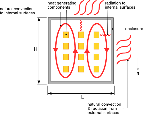
How to calculate the temperature rise in a sealed enclosure

Often times electrical or electronic components are housed in sealed enclosures to prevent the ingress of water, dust or other contaminants. Because of the lack of ventilation in these enclosures all of the heat generated by the internal components must be dissipated through the walls of the enclosure via conduction then from the external surface of enclosure to the environment via radiation and natural convection as shown in figure 1.

sealed_enclosure_diagram
Figure 1. Heat transfer from a sealed enclosure with heat generating components

Accurately calculating the temperature rise of each component housed inside the enclosure is a complicated task that is best accomplished using computational fluid dynamics and heat transfer software. However in many cases being able to estimate the average air temperature within the enclosure based on the dimensions and the material of the enclosure is sufficient information to allow you to develop a design that can be further refined through testing.
continue>>

30 Aug

How to design a flat plate heat sink

A heat sink is a part that conducts heat from a heat generating component to a larger surface area to dissipate the heat to the surroundings thus reducing the temperature of the component. Based on this definition anything from a rectangular sheet of metal to a complex finned copper or aluminum extrusion can be used as a heat sink. In situations where there is ample space and/or the heat dissipated by the component is low an aluminum or copper plate can be used as an effective heat sink. The heat sink can be a simple plate or the metal wall of the enclosure housing the component as shown in figure 1.

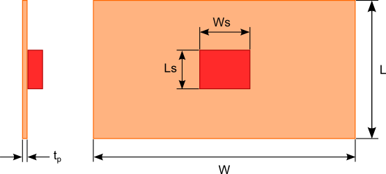
flat_plate_heatsinkFigure 1. Flat plate heat sink dimensions

To estimate the dimensions of the flat plate heat sink you need to determine the path of heat flowing to the surroundings and the magnitude to which that path resists the flow of heat. The thermal resistance circuit shown in figure 2 will be used to represent the path of heat flow. Let’s examine each of the thermal resistance elements:

thermal_resistance_circuit

Figure 2. Thermal resistance circuit of a flat plate heat sink
continue>>