How to calculate the thermal resistance of a PCB
Thermal management is a crucial aspect of designing and manufacturing electronic devices, as heat generated by the components can lead to performance issues and even device failure. To ensure the reliable and efficient operation of electronic devices it is essential to understand how to effectively dissipate heat away from the heat generating devices. These heat generating components are often mounted on printed circuit boards (PCBs) which in many cases are used as a heat sink to cool the attached component.
Thermal resistance is a measure of how well a material or device transfers heat to its surroundings and is often used to predict the thermal performance of a PCB and to calculate the temperature of the attached component. This technical article will provide a detailed explanation of the formulas and method used to calculate the thermal resistance of a PCB. The calculation methodology will take into account the PCB insulation (FR4)/copper layer thicknesses, percent copper coverage in each layer, location of these layers with respect to the heat generating component and usage of thermal vias.
Layout and structure of the PCB
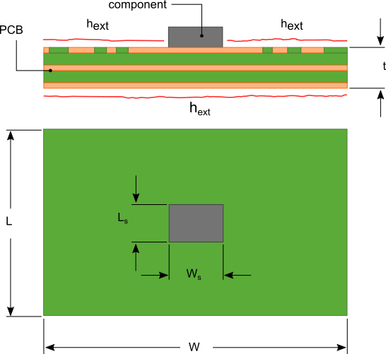
A PCB consists of alternating layers of dielectric and conductive materials typically made using FR4/resin and copper respectively as shown in figure 1. Layers that are used for ground planes often are 100% conductive material. While the layers with attached components, traces and interconnects will have some mixture of conductive and dielectric materials.
Figure 1. PCB layout

