
Selecting the best type of heat sink for your application
The need for heat sinks with increased cooling capacity has been driven by the ever increasing heat generation of electronic devices. This has led to the increased manufacture of pin fin heat sinks as shown in figure 1 that vendors claim has vastly superior performance to the traditional plate fin heat sink with continuous parallel fins as shown in figure 2. Is this claim true? Like most engineering answers….it depends.
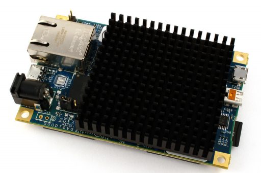 Figure 1. Pin fin heat sink
The goal of a heat sink is to efficiently remove heat from the source(s) it is attached to so as to minimize the temperature of that source(s). The performance of the heat sink is governed by this simple heat transfer equation:

where:


Any heat sink with a larger value of h x A will be able to produce a lower source temperature.

Figure 2. Plate fin heat sink attached to a printed circuit board
A plate fin would almost always for most practical heat sinks have a larger surface area than a pin heat sink that has the same over all dimensions. Only for very closely spaced pin fin heat sinks does the pin fin surface area exceed that of the plate fin heat sink. Don’t believe me? Let’s do the math. Figure 3 shows the dimensions for a pin fin and plate fin heat sinks with the same external dimensions. To make the math easier a heat sink with a square base will be used for the comparison. The equations for the surface areas of the heat sinks are as follows:


Nplate is the number of plate fins and Npin is the number of pin fin along each edge.
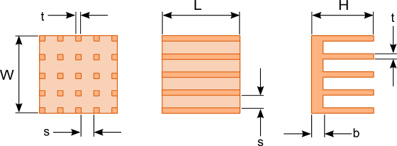 Figure 3. Plate and pin fin heat sink dimensions
The graph in figure 4 shows a plot of the spacing between the fins s versus the surface areas of plate fin and pin fin heat sinks with the following dimensions.
t = 3mm
H = 50mm
L = 50mm
W=50mm
b = 5mm
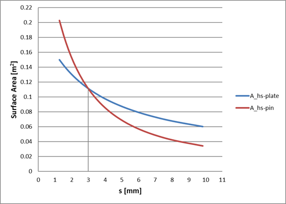
Figure 4. Comparison of the variation of surface area of a pin fin and plate fin heat sink with fin spacing
Only at a fin spacing of approximately 3mm does the Ahs of the pin fin heat sink begin to exceed that of the plate fin heat sink. This fin spacing is quite small for most heat sinks.
If pin fin heat sinks are to out perform plate fin heat sinks then its convection coefficient, h must be sufficiently large to compensate for the lower surface area. The growth of the thermal boundary layer along the direction of air flow is limited by the discontinuous surface formed by the pin fins. As air flows past the fins a thermal boundary layer builds along the surface of the pin. Once the flow of air has reached the gap between pin fins the thermal boundary layer is totally or partially destroyed and reformed when it encounters the next pin fin along the flow path. This destruction of the boundary layer can result in better heat transfer. (Refer to the article Top 3 mistakes made when selecting a heat sink point number 2: “Selecting a heat sink based solely on surface area” for a more detail explanation of the thermal boundary layer. )
The discontinuous geometry of a pin fin heat sink also increases the pressure drop across the heat sink. This increased pressure drop then results in a reduced flow rate particularly in natural convection and in some fan cooled applications where the fan is not directly attached to the heat sink and flow bypass may occur.
There have been a few studies comparing the performance of plate and pin fin heat sinks in natural convection[1], [2]. The results show that for optimized plate and pin fin heat sinks that have the same external dimensions plate fin heat sinks have superior performance in most situations. Pin fin heat sinks are advantageous over plate fin heat sinks in situations where the heat sink may be oriented in multiple orientations. The performance of the pin fin heat sink does not vary significantly in different orientations.
Plate fin heat sinks perform poorly when the fins are oriented perpendicular to the direction of air flow. If the installation of the heat sink is limited to 90° increments then orienting the fins at 45° as shown in figure 5 would create a design that has good performance in all orientations. Note that the performance of a heat sink with 45° angled fins with a length to width ratio of 1.5 is superior to a heat sink with with vertical fins. This is because the cooled ambient air can enter the channels formed by the 45° angled fins along the entire length of the heat sink. The performance of 45° angled fin heat sinks with a length to width ratio below 1 tend to perform slightly worse than a vertical fin heat sink.
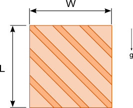
Figure 5. Heat sink with fins oriented 45° to the vertical for better natural convection performance in multiple orientations
Pin fin heat sinks used in for forced convection applications tend to outperform plate fin heat sinks in most situations even considering the increased pressure drop across the pin fins.
Here are some guidelines to help you select the best type of heat sink to use for your application:
- If the orientation of a natural convection cooled heat sink may vary then use a pin fin heat sink.
- If the direction of air flow is unknown for a forced convection cooled heat sink then use a pin fin heat sink since it’s less sensitive to flow direction.
- If substantial air flow rates can be achieved even with a large pressure drop across the heat sink then use a pin fin heat sink.
- For all other situations use a plate fin heat sink. They are less costly, much simpler to manufacture and are readily available in a large range of sizes and configurations.
[1] Younghwan Joo, Sung Jin Kim, “Comparison of thermal performance between plate-fin and pin-fin heat sinks in natural convection,” in: International Journal of Heat and Mass Transfer, Vol. 83, 1995, pp. 345-356
[2] Akshendra Soni, “Study of Thermal Performance between Plate-fin, Pin-fin and Elliptical Fin Heat Sinks in Closed Enclosure under Natural Convection” in: International Advanced Research Journal in Science, Engineering and Technology, Vol. 3 Issue 11, 2016, pp.133-139
